TECHNICAL DATA
H-BEAM TYPES
 |
 |
 |
| 140 H Beam with Wood (For Joist) |
140 H Beam (For Joist & Ledger) |
122 H Beam (For smaller slab thickness) |
140-H BEAM (Alloy 6061-T6)
X-Sectional Area (As) = 1233 mm2
Yield Strength (Fy) = 241 Mpa
Bending Moment (Allowable) = 4.03 KN-m (S.F. = 2.0)
Shear Strength (Allowable) = 59.45 KN (S.F. = 2.0)
122-H BEAM (Alloy 6061-T6)
X-Sectional Area (As) = 1041.92 mm2
Yield Strength (Fy) = 241 Mpa
Bending Moment (Allowable) = 3.19 KN-m (S.F. = 2.0)
Shear Strength (Allowable) = 50.22 KN (S.F. = 2.0)
SPACING TABULATION (FOR 140-H BEAM)
| SLAB THICKNEWW(mm) | IMPOSED LOAD(mm) | JOIST SPACING(mm) | LEDGER SPACING(mm) | PROPS SPACING(mm) |
| 100 | 9.47 | 610 | 2000 | 1400 |
| 150 | 11.15 | 488 | 2000 | 1350 |
| 180 | 12.16 | 488 | 2000 | 1300 |
| 200 | 12.83 | 488 | 2000 | 1250 |
| 250 | 14.51 | 488 | 2000 | 1200 |
| 280 | 15.52 | 488 | 1800 | 1150 |
| 300 | 16.19 | 406 | 1800 | 1100 |
| 350 | 17.87 | 406 | 1800 | 1000 |
| 400 | 19.55 | 406 | 1600 | 1000 |
Imposed load is 1.4 DL + 1.7 LL, where LL is 50 psf + 25 psf impact load.
The suggested ledger and props spacing may very depending on the length of joist and floor height.
Floor height considered in this analysis is 3.6 meters and length of joist is 3.9 to 4.5 meters.

MAIN COMPONENTS & ACCESSORIES
| Diagram | Description | Weight | Article No. |
 |
140-H Beam | 3.15 Kg/m | 2010000 |
 |
140-H Beam with wood | 3.16 Kg/m | 2030000 |
 |
122-H Beam | 2.73 Kg/m | 2040000 |
 |
A Clamp | 0.11 Kg | 7000000 |
 |
U-head | 2.55 Kg | 0500001 |
 |
Swivel coupler | 1.20 Kg | 0500002 |
 |
Props 3.6m | 17.32 Kg | 3102136 |
 |
Tri-pod | 5.32 Kg | 3000018 |
PROJECTS


DESCRIPTION
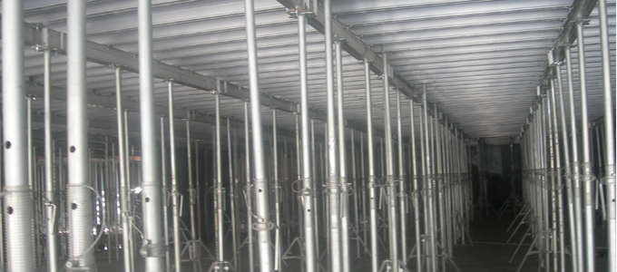
Shoring Props Form system provides simple but effective beam and slab decking for conventional casting works. This system is the best alternative where the Table Form System is not applicable. It can be assembled and stripped easily for fast operations for various concrete slab design structures. Minimum number of manpower can be use but optimum productivity can be achieved.
Basically, the main Components for this system are the aluminum 140-H Beam which acts as joist and ledger for the plywood decking, and the Heavy duty adjustable steel props which carry all the imposed load.
Main Advantages
|
|
System Main Parts
- Alu 140-H Beam Joist
- Alu 140-H Beam Ledger
- Heavy Duty Adjustable Props
- U-head Assembly
- Tri-Pod assembly
- Plywood

The U-head and Tri-pod assembly are non load-bearing components. The U-head is use to hold the 140-H beam ledger in position and the Tri-pod holds vertically the Heavy Duty Props during assembly.
This makes the installation very easy with minimum labor needed. The Tri-pod can be dismantled and used in other area after the props have been securely installed and braced.
Assembly Procedure
Step 1 Mark the layout for the props as per spacing provided in the construction drawing.
Step 2 Position the first and last props vertically with the aid of the Tri-pod and install a U-head on top.
Step 3 Install the 140-H beam ledger on top of the U-head whereas the ledger is supported on both ends.
Step 4 Raise the end props to required height and install the other props in between.Simultaneously,install the joist on top of the ledgers.
Step 5 Repeat the procedure 1 to 4 until the ledgers and joist are completely installed.
Step 6 Install the plywood and fix it moderately on top of joist so that it can easily dismantled after casting.
Step 7 Install end flhlers,side forms lateral bracings and safety railings.
Step 8 Check if everything is completely installed and tightened securely.
Step 9 After other sub-trades are finish with their work,then the slab and beam decking is now ready for casting.
Stripping Procedure
Step 1 Remove the bracing and some props,lower end props while removing loose plywood joist.
Step 2 Strip the plywood attached to the slab with the use of a crowbar.
Step 3 Remove the remaining joist,ledger and props safely avoid accident and damage to the materials.
Step 4 Stack the same materials together so that transferring them to the next casting area will be hassle free.
Step 5 Fix and clean bended and cemented H-beam and props in between castings.